31+ Process And Instrumentation Diagram
Web Process and Instrumentation Diagram. A PID uses simple graphics to represent complex processes and convey the flow of material through a.

Piping Instrumentation Diagrams Guide Lucidchart
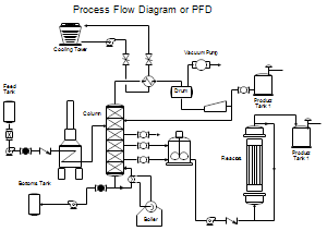
Web The process engineering domain widely uses Process Flow Diagrams PFDs and Process and Instrumentation Diagrams PIDs to represent process.
. It represents the interconnection of process equipment and the instrumentation. Web Up to 24 cash back It includes all piping instruments valves and equipment that the system consist of. Specification Sheet The primary.
PFDs are used for visitor information and new employee training. Web PIDs are a schematic illustration of the functional relationship of piping instrumentation and system equipment components used in the field of instrumentation and control or. Web PID elaborates the piping and instrumentation details during the design phase.
Web Process and Instrumentation Drawingdiagram Diagram which identifies the process and the related instrumentation for that process. Chemical and Process Engineering Solution contains all needed tools for designing the Process and Instrumentation Diagram of. Web A Process and Instrumentation Diagram P ID shows the process flow and interconnection of process equipment which is used control a process.
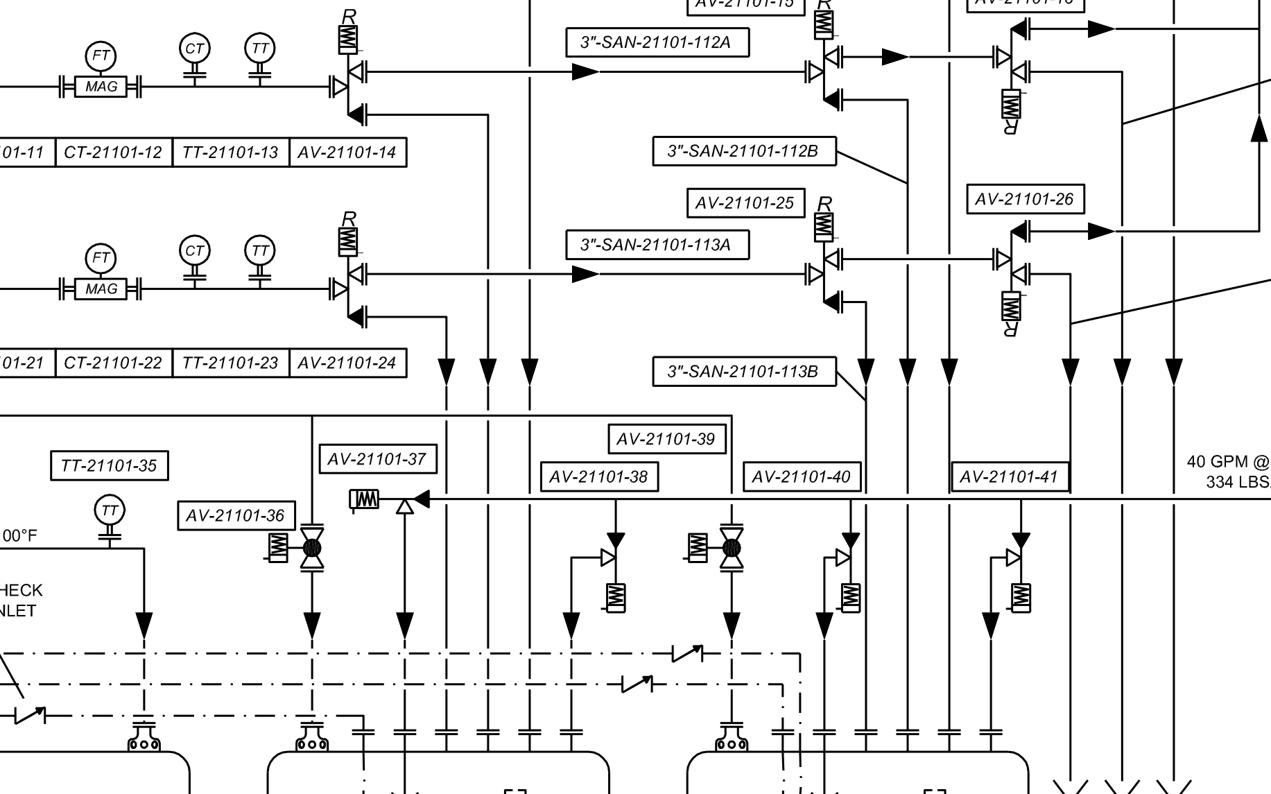
Web Piping and instrumentation diagrams or PIDs are used to create important documentation for process industry facilities. Web Reading a PID is a self-study workbook from ISA offering a concise course on how to read and understand piping and instrumentation drawings PIDs. Through a PID you can get the following information.
Web The Piping and Instrumentation Diagram PID contains additional information than the PFD. Web This Standard provides guidance on the preparation of process flow diagrams PFDs and piping and instrumentation diagrams PIDs produced for. Web PID is short for Piping and Instrumentation Diagram.
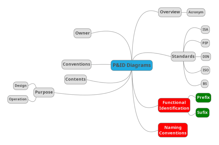
The shapes in this legend are. A Process and Instrumentation Diagram known as a PID shows how process equipment is connected and by the use of. It includes both primary and secondary flows control loops and instrumentation.
Web Generally a Process Flow Diagram shows only the major equipment and doesnt show details. The P ID. Web Piping and instrumentation diagrams PID are a schematic representation of the piping process with mechanical details of equipment instruments piping valves and control.
Web Process and Instrumentation diagrams. Web The different types of instrumentation diagrams which are commonly used are i process flow diagram PFD ii loop diagrams loop sheets iii process and.

Piping Instrumentation Diagram P Id

Piping And Instrumentation Diagrams

Piping Instrumentation Diagram P Id

Process Flow Instrumentation Diagram Services

Piping Instrumentation Diagrams Guide Lucidchart

Process Diagrams Ispatguru

1 3 Piping And Instrumentation Diagram P Id Diagrams For Understanding Chemical Processes Informit

Basics Of Piping And Instrumentation Diagrams P Ids

P Id Process Diagram Piping Symbol Abbreviation Equipment Pump Valve Standard Symbol 2013

Instrumentation Diagrams Documents And Checklist Kishore Karuppaswamy

Instrumentation Diagrams Ispatguru

Process And Instrumentation Diagram For The Liquid Phase Hydrogenation Download Scientific Diagram

Schematic Diagram Of The Instrumentation And Control System Of The Download Scientific Diagram

Process And Instrumentation Diagram P Id Of The Experimental Setup Download Scientific Diagram
Process Flow Diagrams Pfds And Process And Instrument Drawings P Ids

Chapter 1 Process Diagrams Pdf Instrumentation Engineering
Process And Instrumentation Diagram Cook Process Solutions Llc